
- Overview
- Recommended Products
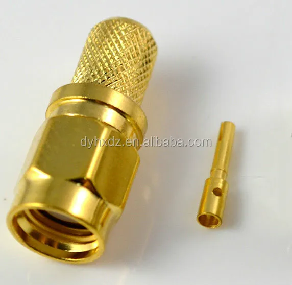
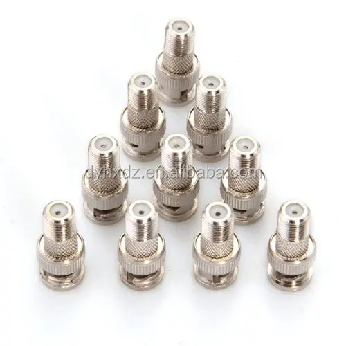
Product Description
Specifications
1.Body:Brass/Gold Plated
2.Insulator: PTFE
3.Certification: RoHS/ISO9001:2008
4.Impedance:50 ohm
5.Frequency Range:0-18GHz
Features & Benefits
| Broadband performance DC to 18 GHz with low reflection stainless steel construction and ¼ - 36 threaded coupling offers high performance in a compact design. | |
| Low cost Commercial Grade (Brass SMA) available in nickel or gold plating which provides approximately 30% cost reduction with 250 mating cycles. | |
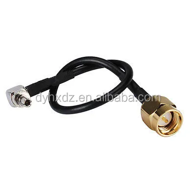
| Available for .085" and .141" diameter semi-rigid cables and all the standard flexible cables including double shielded RG-316. | |
| Phase Adjustable SMA connectors provide ease of mechanical screw adjustments, compared to the delays and expense of laborious cable-trimming. |
Applications
| Base Stations | Cable Assemblies | Components | |||
| Instrumentation | Mil/Aero | PC/LAN | |||
| Process Controls | Telecom |
Brass SMA Specifications
| Electrical | |
| Impedance | 50 Ω |
| Frequency Range | .141" & .085" semi-rigid cable: 0-18 GHz Flexible cables: 0-12.4 GHz |
| Voltage Rating | RG-58, 141, 142: 500 volts peak RG-174, 188, 316: 375 volts peak |
| Dielectric Withstanding Voltage | .141" & RG-58 Cables: 1,000 VRMS .085" & RG-316 Cables: 750 VRMS |
| VSWR | Straight connector, .141": 1.05 + .005 f (GHz) Straight connector, .RG-174: 1.15 + .02 f (GHz) Straight connector, RG-58: 1.15 + .01 f (GHz) Straight connector, RG-178: 1.20 + .025 f (GHz) |
| Contact Resistance | Center contact: 2.0 mΩ Body: 2.0 mΩ Braid to body: 0.5 mΩ |
| Insulation Resistance | 5,000 MΩ |
| Insertion Loss | dB maximum = .06v[f(GHz)] Test frequency @ 6.0 GHZ |
| RF Leakage | -90 dB minimum @ 2.3 GHz |
| Mechanical | |
| Mating | .250-36 threaded coupling |
| Mating Torque | Minimum: 2 inch pounds (12 N.cm) Recommended: 7-10 inch pounds (80-110 N.cm) Maximum: 15 inch pounds (170 N.cm) |
| Connector Durability | 100 matings |
| Material | |
| Bodies, Coupling Nuts, Other Metal Parts (except as noted) | Brass per QQ-B-626 |
| Contacts | Male: Brass Female: Beryllium copper, heat treated |
| Center Contact Plating | .000030" minimum gold |
| Plating (Other Metal Parts) | Standard .000010" gold or nickel plated |
| Insulator | TFE fluorocarbon |
| Gaskets | Silicone rubber |
| Crimp Ferrule | Seamless copper tubing alloy |
| Environmental | |
| Temperature Range | - 65°C to +165°C |
| Thermal Shock | MIL-STD-202 method 107 (test condition B) except high temperatures @ + 200°C |
| Vibration | MIL-STD-202 method 204 (test condition D) |
| Shock | MIL-STD-202 method 213 (test condition I). No discontinuity permitted. |
| Corrosion | MIL-STD-202 method 101 (test condition B) 5% salt solution |
| Moisture Resistance | MIL-STD-202 method 106, except step 7b (vibration) omitted, and high humidity measurements do not apply |
| Weatherproofing | Crimp type: heat shrink tubing Solder type: silicone rubber gaskets |
| Altitude | MIL-STD-202 method 105 (test condition C), no corona at 70,000 feet. .141" & RG-55: 250 VRMS .085" & RG-122: 190 VRMS |
| Military Specifications | |
| MIL-C-39012 & MIL-C-83517 SMA Specification Sheets | As applicable |
Note: These characteristics are typical but may not apply to all connectors.