
- Overview
- Recommended Products
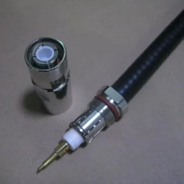
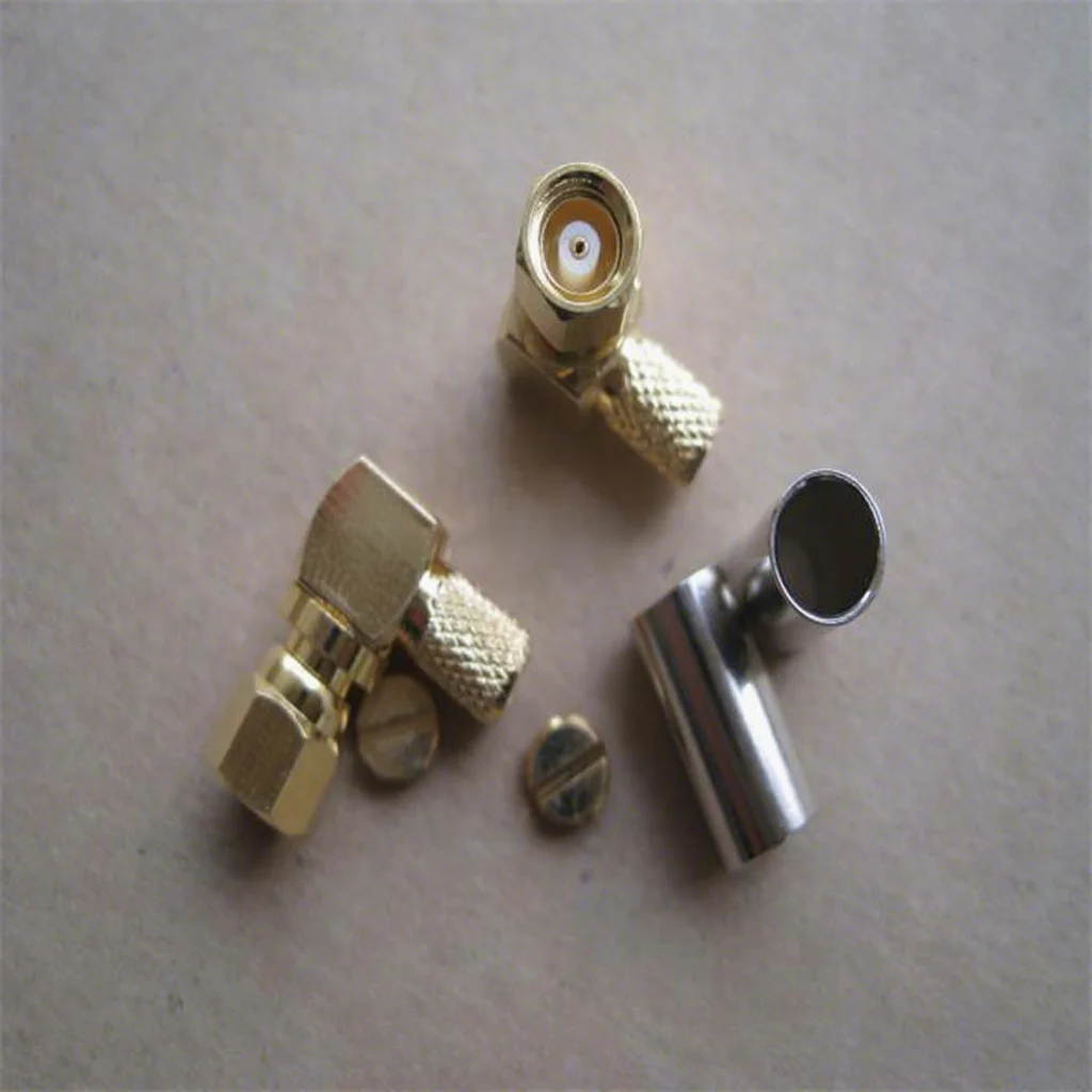
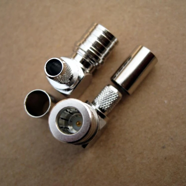
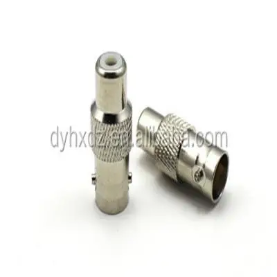
Micro-Miniature Coax MMCX Female RF Connector With Microstrip For Printed Circuit Board
Features & Benefits
| • | Broadband performance with low reflection DC to 6 GHz, providing a high-quality solution at a low cost |
| • | Quick connect/disconnect snap-on mating reduces installation time |
| • | Conforms to European CECC 22000 specifications |
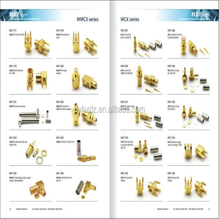
| • | Available in straight and right angle plugs and printed circuit board connectors |
Applications
| • | Antennas | • | Base stations | • | Broadband communications |
| • | Cable assemblies | • | Components | • | GPS |
| • | Instrumentation | • | PCMCIA cards | • | Radio boards |
| • | Satcom | • | Telecom |
MMCX Specifications
| Electrical | CECC 22000 | |
| Impedance | 50 ohms | |
| Frequency Range | DC - 6 GHz | |
| VSWR | 4.4.1 | 1.15 max. @ DC - 4 GHz |
| 1.40 max. @ 4 - 6 GHz | ||
| RF-Leakage | 4.4.8 | 60 dB minimum @ 1 GHz (flexible cable) 70 dB minimum @ 1 GHz (semi-rigid cable) |
| Voltage Rating (at sea level) | ≤ 170 Vrms (depending on cable) | |
| Contact Resistance | 4.4.2 | center contact: ≤ 10 mohms |
| 4.4.3 | outer contact: ≤ 5 mohms | |
| Insulation Resistance | 4.4.4 | 1,000 Mohms minimum |
| Dielectric Withstanding Voltage | 4.4.5 | 500 Vrms (at sea level) |
| Mechanical | CECC 22000 | |
| Mating | Snap-on coupling | |
| Contact Captivation | 4.5.2 | 2.3 lbs |
| Engagement Force | 4.5.4 | ≤ 3.4 lbs (15N) |
| Disengagement Force | 4.5.4 | ≥ 1.4 lbs (6N) |
| Durability (matings) | 4.7.1 | 500 cycles minimum |
| Environmental | CECC 22000 | Test Requirement |
| Temperature Range | 4.6.5 | -55° C to +155° C |
| Thermal Shock | 4.6.7 | MIL-STD-202, method 107, cond. F |
| Moisture Resistance | 4.6.6 | MIL-STD-202, method 106 |
| Corrosion | 4.6.10 | MIL-STD-202, method 101, cond. B |
| Vibration | 4.6.3 |
3 cycles, 3 opposite directions, 10 - 150 Hz 10 - 60 Hz: 0.75mm/0.03in., 60-150 Hz: 10 G |
| Mechanical Shock | 4.6.4 | MIL-STD-202, method 213, cond. B |
| Humidity | 4.6.6 |
MIL-STD-202, method 103, cond. B |
| Material | CECC 22000 | Test Requirement |
| Body and Outer Contacts | Brass, nickel or gold plated | |
| Male Contact | Brass, gold plated | |
| Female Contact | Beryllium copper or phosphor bronze, gold plated | |
| Crimp Ferrule | Copper or brass, nickel plated | |
| Insulator | LCP, PTFE or PFA |
Note: These characteristics are typical but may not apply to all connectors.